
I have a nostalgic itch for DEC things. So at RetroFest 2025 in Swindon I was handed this very dead AlphaStation 500 in case I might be able to revive it. Although, looking at the previous owner’s account, my chances are very slim indeed.
Frankly, having taken a look inside, I can’t blame it for having no will to live. The quality of design and attention to detail is abysmal. Things always feel it when they are not designed with love.
As you may recall, Alphas have eight bootstrap images in ROM, which is called Serial ROM (SROM) because the images are serialised as bit streams. The image to load at reset is selected by fitting a jumper to one of a series of eight jumper positions on the mainboard. One of them is a normal boot image, the others are for diagnostics.
On the AlphaStation 500, these jumper positions are numbered J11…J17 and J19. For whatever happened to J18, the board designer obviously thought it was alright. Who cares. Let’s just assign random designators, nobody’s going to diagnose this thing anyway.
To really drive this point home, the jumpers are located so as to make them inaccessible:


Squeezed tightly between the RAM and power connectors, they sit directly underneath a partition wall. Compare that to the DEC 3000 AXP, designed just three years earlier:

DEC 3000 Model 800 AXP SROM selection jumpers
Diagnostic LEDs have been a ubiquitous feature of DEC computers since the PDP series. Their purpose is to indicate start-up progress and failures before the console output is available. This could be a simple row of 8 red LEDs that you’d read in binary, or a pair of TIL311 hexadecimal digits for that sophisticated high-end look.

The AlphaStation 500 has got neither. Why bother? If it ain’t working, toss it in the bin — such was the design trend at the time. Or better yet, give it to a scrapper so that the bloody thing gets the treatment it deserves and will never surface again.
In an ironic twist of fate, though, the 500 got those signals broken out onto a pin header connector compatible with the Flamingo LSM — Lights and Switches module. Was it really cheaper than 8 surface mounted LEDs?

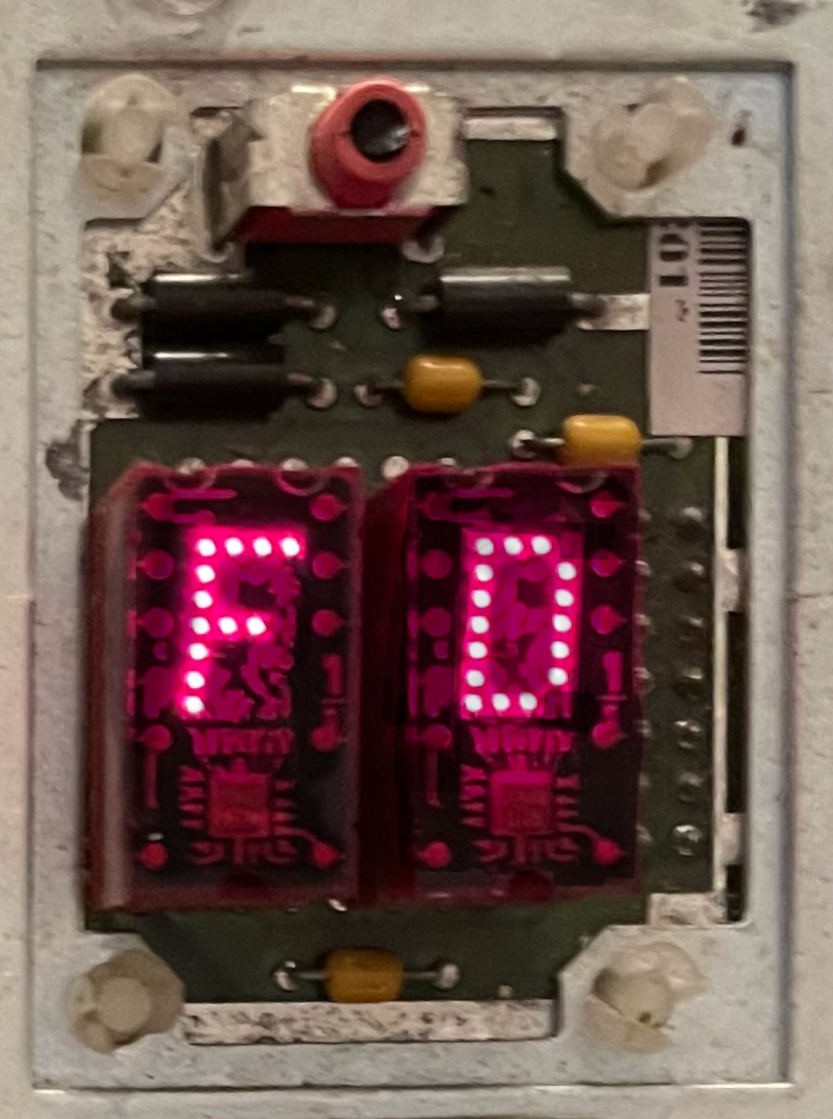
Now, my other Alpha just happens to be a Flamingo. I borrowed its LSM, plugged it in, and it worked. It shows DE when I switch the machine on. So there is some life in this AlphaStation.
Here is the LSM connector pinout when viewed as in this picture, i.e. with the front of the machine pointing to the right:
| bit 0 | bit 3 | bit 5 | bit 6 | GND | GND | GND |
| bit 1 | bit 2 | bit 4 | bit 7 | +5V |
I believe bit 1 is on pin 1 on the connector. The two unlabelled pins above are for the HALT button on the Flamingo.
Bits [7..0] represent the diagnostic code at 5V TTL levels so can be sampled with a voltmeter or a logic analyser.

The machine is equipped with two Dallas modules: a DS1287 real-time clock and a DS1225AD-150 nonvolatile SRAM. Each has a non-rechargeable battery cell inside the package.
In a strong FU message to the owner, these are soldered onto the mainboard. Not socketed, like on earlier machines. So what do you do in 3–5 years when the batteries go flat? That’s right — toss it in the bin! Have you got a computer system with a non-socketed Dallas module? Leave a comment below!
The year is 1996. DEC has less than two years to live. Top management is frantically selling off assets to make what’s left of the company palatable for Compaq to swallow. Quick, cheap, and with a PCI bus — that must’ve been the design brief given to the handful of engineers still lingering about after a series of layoffs. Poor and sad AlphaStations rolling off the production line struggle to understand why they were made at all.
Okay, digression aside, let’s see whether we can find out what’s wrong with this machine. It stops with the DE code on the diagnostic LEDs. According to AlphaStation™ 500 Series User Information (P/N EK-ALPH5-UI.B01), it’s the second step of the initialisation sequence:

It hangs without detecting an error, as errors would have displayed their own codes in the E0–FF range. I’ve probed RAS and CAS signals on the memory but have seen no activity. So either the fault is in the CPU/system interface, or there’s more going on than what the documentation implies.
Alpha systems are equipped with a debug and diagnostic port, which is a 10-pin connector providing a software UART interface. Its RX and TX pins are connected to the processor with a minimum amount of glue logic, so that the SROM code can implement basic communication using a software timing loop.
On earlier Alphas, SROM would print something out first thing before attempting any off-chip initialisation. I was expecting the same behaviour on this 500, but the TX pin on J24 was dead. Even though the code managed to run as far as getting the DE code out on the LEDs, there was no activity on the debug port.
As it turned out, the reason was that the SROM code did not know the CPU clock frequency and thus could not configure its timings for the appropriate baud rate. Whilst the clock speed was hardcoded on earlier Alpha systems, at some point having multiple SROM images for different frequencies had become impractical.
On these newer systems, the SROM code has to determine the CPU speed before using the debug port. The typical procedure is to initialise the Dallas RTC periodic interrupt at the rate of 1024 Hz and measure the CPU clock off that. The DS1287 RTC sits on the X-bus, which is attached to EISA, which is in turn attached to PCI, which is behind the Digital Semiconductor 21172 core logic chipset:
CPU — 21172–CA —PCI— Intel 82375SB+82374SB —EISA— buffer —X-bus— Dallas 1287
So pretty much the entire system needs to be initialised for the SROM debug port to become usable. Might as well use the normal serial console port at this point. Well, almost.
SROM image number 7, which can be selected by jumper J19, is described as a ‘No init mini console’. With that, we could expect to see some output on J24, as long as the code truly did not attempt to initialise anything.
Alas, still nothing. However, another owner of a dead AlphaStation 500 explained what happened. Since the software still needs to guess the CPU speed, the no-init variant times it off the RX signal on the SROM debug port. It expects the user to type ‘U’ (55 hex), which sends a series of alternating zeros and ones, acting as a time reference.
No input validation is done. The program simply waits for 10 transitions on the RX input, timing them as they arrive. If you type anything else, the calculated speed will end up too far off for the SROM output on TX to make any sense at all.
Now, the no-init console indeed springs to life on receiving the ‘U’:
Bret SROM V2.05
000003ea MHz
Console

SROM>
This tells us two things.
Bret SROM V2.05
000001f5 MHz
Console

SROM>
Okay, we seem to be getting somewhere…